Verilog 5Hz clock with blinking LED
Introduction
We need this project to
test the I/O pins of the board and the clock of the board
save it as symbol, so we can use it as a component to get 5Hz clock in schematic mode.
References:
- http://iemontiel.blogspot.my/2015/07/mi-aventura-para-elaborar-un-componente.html
- http://jasperfracture.com/altera-c-m240-tutorial-using-verilog-code-with-block-schematics/
Create New Project for MAX II EPM240T100C5
Open Quartus II 9.1
Click File->Create New Project
Click Next
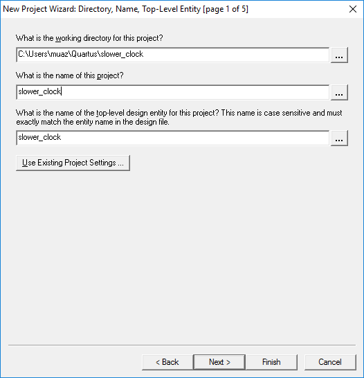
In page 1 of 5, set the project details:
- working directory: C:/Users/<your-username>/Quartus/slower_clock
- name of the project: slower_clock
- top level design entity: slower_clock
Click Next, and Next again (skipping page 2)
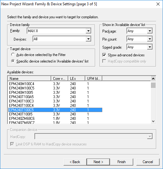
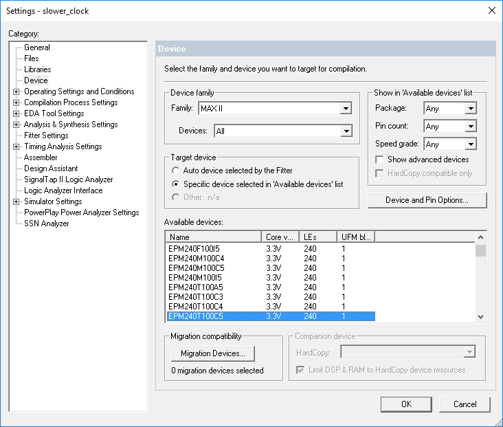
In page 2 of 5, set the hardware
We are using EPM240T100C5,
Hence, Select
- Device family: MAX II
- Devices: All
- Available Devices: EPM240T100C5
Click Next, Next, Next, Finish
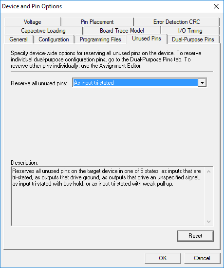
Set Unused Pins as Tri-state
We also need to set unused pins as tri-state, else if default is used (ground), it may be harder to debug program after programming (e.g. LED on even if no signal)
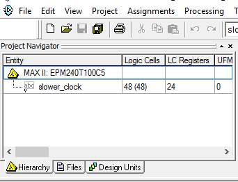
Click the name MAX II: EMP240T100C5 (with the pyramid symbol
Click Device & Pin Options
Then under Unused Pins tab, Set Reserve all unused pins: As input tri-stated
Create Verilog File and Compile the file (Analysis & Synthesis)
Click File->New..
Select Verilog HDL File
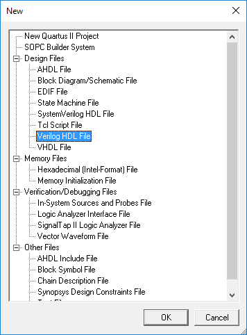
You will be given a text editor,
Paste the following:
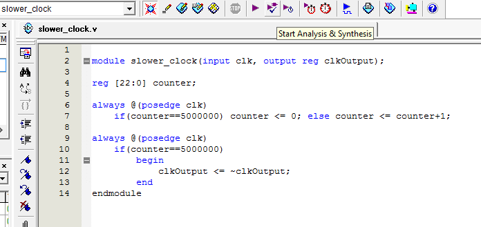
For the project be able to compile, the module name must be the same as set during the project set up. In this case, slower_clock
module slower_clock(input clk, output reg clkOutput);

reg [22:0] counter;

always @(posedge clk)
    if(counter==5000000) counter <= 0; else counter <= counter+1;

always @(posedge clk)
    if(counter==5000000)
        begin
            clkOutput <= ~clkOutput;
        end
endmodule
What the code does is:
- set a module with input clk, output clkOutput
- create a 23-bit register called counter
- Assuming the global clock is 50MHz and we want 5Hz clock
- using formula global clock frequency / desired frequency / 2 = counter end value
- counter end value = 50e6/5/2=10e6/2=5,000,000
- during positive edge, increase counter by one, when it reaches 5,000,000 reset back to 0 in non-blocking assignment.
- during positive edge, if counter is 5,000,000 set clkOutput as NOT clkOutput.
- using formula global clock frequency / desired frequency / 2 = counter end value
Save the file, click Start Analysis & Synthesis button. Wait for compile to finish.
Set The I/O Pins using Pin Planner
On the tool bar, click Pin Planner

You will see this window:
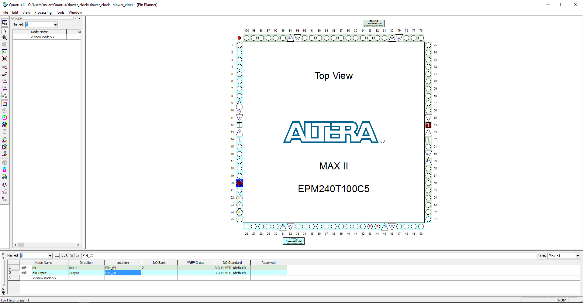
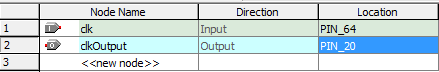
Set the location of pins
- clk: 64
- clkOutput: 20
Note: If after compiling and programming, LED does not blink, try pin 12, 14, or 62 instead. The crystal oscillator may be connected to different pin.
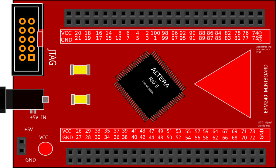
Connect the I/O pins to LED
On your board, Connect to Pin 20 of the CPLD board to an LED with resistor. Use breadboard and male-female jumper wires to complete the connection.
Here is the I/O pin layout of the CPLD. Pin 20 should be at top row, second column from left.
Image taken from http://iemontiel.blogspot.my/2015/07/mi-aventura-para-elaborar-un-componente.html
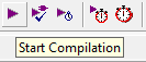
Compile (full compilation) and Program to CPLD
Go to main window, click Start Compilation.
Wait compile to finish.
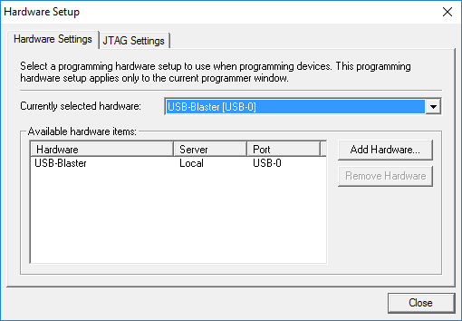
Then click Programmer
In Programmer Window Under Menu bar, Click Hardware Setup, the set to USB-Blaster
Then for the Program/Configure column, check all box for the compiled .pof file and CFM, UFM
Finally, click Start and wait for the programming complete
Results
See if your LED is blinking at 5Hz.
If LED lights up but did not blink, try using other clock pins (12, 14, 62)
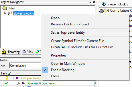
Create Symbol for the slower_clock
We need to do this so that this slower_clock module is available as a symbol for other project that use Schematic diagram.
Under project navigator, click Files tab, then right click at slower_clock.v, select Create Symbol Files for Current File